Kia Rio: Engine Control System / Intake Air Temperature Sensor (IATS)
Specifications
| Specification |
Intake Air Temperature Sensor (IATS)
▷ Type: Thermistor type
|
Temperature |
Resistance (kΩ) |
|
|
°C |
°F |
|
|
-40 |
-40 |
40.93 - 48.35 |
|
-30 |
-22 |
23.43 - 27.34 |
|
-20 |
-4 |
13.89 - 16.03 |
|
-10 |
14 |
8.5 - 9.7 |
|
0 |
32 |
5.38 - 6.09 |
|
10 |
50 |
3.48 - 3.90 |
|
20 |
68 |
2.31 - 2.57 |
|
30 |
86 |
1.9 - 2.1 |
|
40 |
104 |
1.08 - 1.21 |
|
50 |
122 |
0.76 - 0.85 |
|
60 |
140 |
0.54 - 0.62 |
|
70 |
158 |
0.40 - 0.45 |
|
80 |
176 |
0.29 - 0.34 |
|
90 |
194 |
0.22 - 0.26 |
|
100 |
212 |
0.17 - 0.20 |
|
110 |
230 |
0.13 - 0.15 |
|
120 |
248 |
0.10 - 0.12 |
|
130 |
266 |
0.08 - 0.09 |

Description and operation
| Description |
Intake Air Temperature Sensor (IATS) is included inside Manifold Absolute Pressure Sensor and detects the intake air temperature.
To calculate precise air quantity, correction of the air temperature is needed because air density varies according to the temperature. So the ECM uses not only MAPS signal but also IATS signal. This sensor has a Negative Temperature Coefficient (NTC) and its resistance is in inverse proportion to the temperature.

Schematic diagrams
| Circuit Diagram |

Repair procedures
| Inspection |
| 1. |
Turn ignition switch OFF. |
| 2. |
Disconnect IATS connector. |
| 3. |
Measure resistance between IATS terminals 3 and 4. |
| 4. |
Check that the resistance is within the specification.
|
|||||||||||||||||||||||||||||||||||||||||||||||||||||||||||
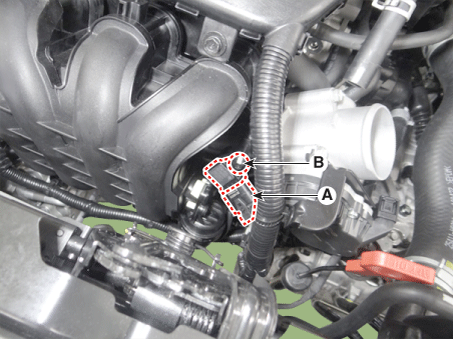
| Removal |
| 1. |
Turn ignition switch OFF and disconnect the battery negative (-) terminal. |
| 2. |
Disconnect the manifold absolute pressure sensor connector (A). |
| 3. |
Remove the installation screw (B), and then remove the sensor from the surge tank.
|
| Installation |
|
| 1. |
Installation is reverse of removal. |
Troubleshooting
| Waveform |

 Manifold Absolute Pressure Sensor (MAPS)
Specifications
Specification
Manifold Absolute Pressure
Sensor (MAPS)
▷ Type: Piezo-resistive pressure sensor type
Pressure
[kPa (kgf/cm², psi)]
Outp ...
 Engine Coolant Temperature Sensor (ECTS)
Specifications
Specification
Engine Coolant Temperature
Sensor (ECTS)
▷ Type: Thermistor type
Temperature
Resistance (kΩ)
°C
...
Other information:
Kia Rio 2017-2025 YB Owners Manual: Icy Road Warning Light
This warning light is to warn the driver the road may be icy. When the following conditions occur, the warning light (including Outside Temperature Gauge) blinks 5 times and then illuminates, and also a warning chime sounds once. - The temperature on the Outside Temperature Gauge is below appr ...
Kia Rio 2017-2025 YB Service Manual: Fuel Filler Cap
Description and operation Description A ratchet tightening device on the threaded fuel filler cap reduces the chances of incorrect installation, which would seal the fuel filler. After the gasket on the fuel filler cap and the filler neck flange contact each other, the ratchet prod ...


