Kia Rio: Light bulbs / Tail lamp (inside) bulb replacement (for 5 door)

1. Open the liftgate.
2. Remove the service cover.
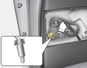
3. Remove the socket from the assembly by turning the socket counterclockwise until the tabs on the socket align with the slots on the assembly.
4. Remove the bulb from bulb-socket by pulling it out.
5. Insert a new bulb by inserting it into the bulb-socket.
6. Install the socket in the assembly by aligning the tabs on the socket with the slots in the assembly. Push the socket into the assembly and turn the socket clockwise.
7. Install the service cover by putting it into the service hole.
1. Open the liftgate. 2. Remove the service cover. 3. Remove the socket from the assembly by turning the socket counterclockwise until the tabs on the socket align with the slots on the assembly.
1. Open the liftgate. 2. Remove the service cover. 3. Loosen the light assembly retaining screws with a cross-tip screwdriver. 4. Remove the rear combination lamp assembly from the body of the vehicle.
Other information:
Kia Rio 2017-2023 YB Service Manual: Power Window Switch
Components and components location Components Driver Power Window Switch Connector Pin Information [Front / Rear Driver Safety - Auto Up/Down] [LHD] No. Description No. Description 1 Front right power window (Up) 10
Kia Rio 2017-2023 YB Service Manual: Front Wiper Motor
Components and components location Component Location 1. Cap 2. Nut 3. Wiper arm & blade 4. Cowl top cover 5. Bolt 6. Wiper motor & linkage assembly 7. Wiper motor connector Repair procedures Removal 1.
Categories
- Manuals Home
- Kia Rio Owners Manual
- Kia Rio Service Manual
- Clutch System
- Cooling System
- Engine Control / Fuel System
- New on site
- Most important about car
